AutoCAD Tips and Tricks - Draw1. Ways to Draw at a Specified Angle
Using old and new tools you can draw aligned lines and modify objects at specified angles in various ways.
@ Expressions
Using old @ expressions still works fine, if you are used to them. @ stands for relative input.
1. @x,y - x and y stand for distances in x and y directions from the last specified point in your drawing. Pay attention to positive or negative x and y directions. 2. @distance<angle - distance value is relative from the last specified point in your drawing. Pay attention to positive or negative angle directions. Dynamic Input
If you turn on the Dynamic Input button on your status bar, you can type relative x, y and angle inputs without @ character. Press Tab to activate the input you want.
Polar Tracking
Using Polar Tracking you can constrain your cursor movement into predefined angles. Exact angle direction is visualized by a long dotted line and a measurement angle.
1. Status Bar / Turn on Polar Tracking button. 2. Shortcut menu on the Polar Tracking button / Settings / Drafting Settings dialog box
3. Polar Tracking / Set an Increment Angle (cursor will be constrained at its multiple angles) 4. Additional angles – Cursor will be constrained only at a given angle. 5. Polar Angle measurement / Absolute (angle measurement from angle 0°). 6. Polar Angle measurement / Relative to last segment (angle measurement from the angle of the last drawn segment). 2. Draw without Construction Lines
What do you do when you have to specify a point that is distant from a different point at a certain distance? Many users draw a construction line and then start of again at its point. When completed, they erase construction line. Well, AutoCAD offers much faster and easier ways to do this, without using construction lines.
Object Snap Tracking (Otrack)
Using this function you can mark certain points on your geometry and continue to draw in their projection. For example, you can mark 2 points and follow their projection to find its intersection point without drawing any construction lines. Marking points with Otrack works in conjunction with object snaps, therefore make sure, that you also turn on and set Object Snap. E.g. to specify a center point of a circle right in the center of rectangle follow the next procedure:
1. Status Bar / Turn on Object Snap Tracking button 2. Status Bar / Turn on Object Snap button (set object snaps you want to mark, e.g. midpoint)
3. Click Circle command. 4. Mark midpoints of adjacent rectangular segments by simply hovering over these points (do not click them!). When a point is marked, a cross sign will appear. Move your cursor in projection of these two midpoints close to their intersection. When you see two long intersecting dotted lines, click for center point of a circle. Using Otrack you can also move away from a specified point for a single exact horizontal or vertical distance.
1. Status Bar / Turn on Polar Tracking button 2. Status Bar / Turn on Object Snap button (e.g. endpoint) 3. Mark a point you want to move away from. 4. Move the cursor in the desired direction and type direct distance entry. Tracking
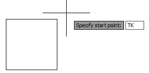
If Otrack moves away from a specified point for only one exact horizontal or vertical distance, Tracking will do the same, but for any number of distances. Unfortunately tracking is an old function and has been removed from the object snap menu, but you can still type its shortening ´TK´ during any command.
E.g. to start drawing 20 units away from the top right corner of the rectangle in both, horizontal and vertical directions, follow the next procedure: 3. Specify first tracking point and click the top right corner of the rectangle.
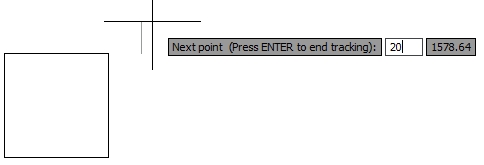
4. Move the cursor in horizontal direction and type direct distance entry (20 units). The segment isn’t drawn, but cursor has moved in pointed direction for a specified distance. 5. Move the cursor in vertical direction and type direct distance entry (20 units). Pointing your cursor in desired direction with active tracking function might sometimes be a bit stiff. Keep close to the last point in your drawing or type 0 length in one direction, and maybe you´ll find it easier to redirect your cursor.
6. When you reach the point you wanted, press ENTER to end tracking. 7. Polyline command will continue being active from that point. 3. Quick Hatch Tips
AutoCAD 2011 offers some new hatch features which can speed up the hatching process, and there are also some useful old ones that aren’t used as often.
Create a Hatch Pattern with Colored Background in One Step
The only way to do this in previous version of AutoCAD was to draw two different hatches (pattern and solid) on top of each other, and then send the solid one to back. In AutoCAD 2011 this can be done in one step.
1. Ribbon / Home tab / Draw panel / Hatch
2. Contextual ribbon Hatch Creation tab / Pattern panel / Select a pattern. 3. Properties tab / Background color drop-down menu / Select a background color. 4. Apply hatch to an object using standard hatch procedure. Display All Hatches behind All Other Objects at Once
Before AutoCAD 2011 you had to send back each selected hatch and new ones as well. Now, you only need one click to send all hatches in your drawing and new ones to back.
Ribbon / Home tab / Modify panel / Draw order drop-down menu / Send Hatches to Back Hatch Non-closed Objects
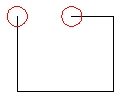
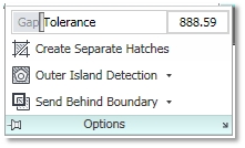
First rule to successfully hatch an object is that its boundary is closed. In other case you get a warning that a closed boundary cannot be determined. Before AutoCAD 2010 you probably had a hard time finding small gaps and fixing boundary so that it is completely closed for successful hatching. This gets easier in later versions as boundary gaps are temporarily graphically shown in red circles after hatch command fails. Ok, so you can quickly find a gap and fix it. But not many users know that a non-closed boundary can be hatched without fixing its gaps. Gap Tolerance specifies the maximum size of boundary gaps to be ignored or if extended, they would close the boundary.
Modify Associative Hatch
Associative hatch will automatically update when you modify its boundaries. Associativity must be turned on when creating a hatch.
1. Ribbon / Home tab / Draw panel / Hatch 2. Contextual ribbon Hatch Creation tab / Options / Associative Modify Non-Associative Hatch
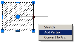
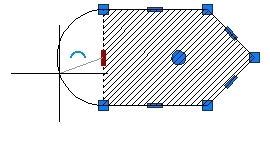
If you forgot to turn on associativity when creating a hatch or you´ve erased its boundary, you can still reshape it using intuitive grips. Some might find this as a quicker way than erasing it, draw new boundary and hatch it again.
1. Select a non-associative hatch in your drawing. 2. Hover over a grip to view all modifying options in shortcut menu: Stretch Vertex, Add Vertex and Remove Vertex. You can also convert center grips to Arc or back to Line. 3. Select one option, e.g. Add Vertex. 4. Left click new vertex to a different location. Turn off Hatch Preview in Large Drawings
Automatic hatch preview when hovering over closed boundaries using ´pick point´ method in AutoCAD 2011 can be quite practical. However, in large drawings it can slow down your process as you might hover over many closed areas to reach your drawing boundary and every hatch preview stops you on your way there. If you want, you can turn off your automatic hatch preview.
Set the system variable HPQUICKPREVIEW to 0. Extra tip: If you turn off your automatic preview, the only way to get one is to determine hatch settings using the old Hatch and Gradient dialog box. Hatch icon on the ribbon will launch this old dialog box, if you set the system variable HPDLGMODE to 1 (to launch the new contextual ribbon Hatch Creation set it to 2). 4. Creating a Circle with a Specified Radius Tangent to Two or Three Objects
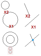
Many users tend to struggle with how to draw a circle tangential to two other circles. Calculating geometry and drawing construction lines can be very time consuming, especially when there is a command already available to do this. Well, it is a bit hidden.
1. Ribbon / Home tab / Draw panel / Circle drop-down menu / Tan, Tan, Radius 2. Click near the tangent of the first circle (tangent snap will automatically switch on) 3. Click near the tangent of the second circle. 4. Press Enter to confirm recommended radius of the new circle or type your own. If you want to create a circle tangent to three objects, click Tan, Tan, Tan command from the Circle drop-down menu. 5. Fast Creation of an Object Similar to the Selected Object
A classical way to draw an object that is the same or similar to the one in your drawing would be to activate the right layer first, then perhaps to make the right Text or Dimension style current, and then finally use the right command. Well, in AutoCAD 2011 all this can be done in a single step.
Add Selected command launches the command which was needed to create a selected object with its defined properties. 1. Select an object in your drawing, e.g. text. 2. Shortcut menu on your drawing area / Add Selected. 3. Command used to draw selected text is launched, e.g. Multiline Text. 4. New text will have the same properties as the one selected, e.g. the same layer, Text properties, etc. 6. Parametric Drawings are More Accurate and Easy to Modify
Parametrical drawing has been introduced to AutoCAD 2010 and is quite a large topic to cover. In general, it means that you can constrain your geometry to establish and maintain its geometric and dimensional relationship after it has been modified. As a result you get an automatic drawing with faster modification and fewer errors. Although it is practically impossible to constrain the whole geometry in large drawings, you might find as a useful tool to help you with some drawing segments.
Geometric Constraints
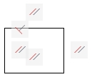
You can geometrically constrain objects, key points on objects or objects to coordinate system, e.g. you can define that two lines are always perpendicular to each other, two circles concentric, two lines equal length, etc. Each constraint in your drawing has its own constraint bar icon, so that you can easily identify them. You can assign geometric constraints to geometry automatically or manually.
Automatic geometric constraints
There are two ways to apply geometric constraints automatically: - Apply geometric constraints while creating and editing geometry: 1. Status Bar / Turn on Infer button - Apply geometric constraints to an object selection:
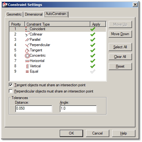
1. Ribbon / Parametric tab / Geometric panel / Auto Constrain 2. Specify the Settings [S] option to open Constraint Settings dialog box. 3. Determine the order and types of constraints to be applied. 4. Select objects to automatically constrain. 5. Constraints are applied based on the orientation of the selected objects relative to one another. Dimensional Constraints
Dimensional constraints control the size and proportions of your drawing. They seem similar to regular dimension lines. However, if dimension lines are controlled by its dimensioned object, a constrained object will be controlled by its dimensional constraints. You can apply dimensional constraints to distances between objects or two points on objects and angles between objects or two points on objects. You can also control radius and diameter of arcs and circles.
Apply dimensional constraints to, e.g. both sides of rectangle: 1. Ribbon / Parametric tab / Dimensional panel / Linear 2. Specify the Object [O] option / Select one segment of a rectangle 3. Specify dimension line location. 4. To confirm the name of dimensional constraint, e.g. d1=, press Enter. Otherwise type your name and an equal sign, e.g. A=, and then press Enter. Control geometry size through dimensional constraints values:
1. Double click the value of dimensional constraint to activate it. 2. Type a new value (300) or even equation (300/2). Equations can relate to other dimensional constraints (A=B*2). Show/Hide and Delete Constraints
Many constraints can visually crowd up your drawing. If you don’t want to see them, you can simply hide them. Though you won´t see them, they will still be applied and they will still control your geometry. You can easily show them back again. But when constraints start to interfere with your geometry you can also permanently delete them.
Hide constraints: Ribbon / Parametric tab / Geometrical or Dimensional panel / Show/Hide or Hide All. Show constraints: Ribbon / Parametric tab / Geometrical or Dimensional panel / Show/Hide or Show All. Delete constraints: 1. Ribbon / Parametric tab / Manage panel / Delete Constraints 2. Select objects with constraints you want to remove permanently. 7. Automate Field Data in Your Drawing
A field is an updateable text linked to different data of your drawing file, geometry, hyperlinks, etc. The biggest advantage of fields is that they get automatically updated whenever you make some changes. So you can save time and avoid making mistakes as you don’t have to modify the data yourself. Many useful field types are already predefined, meaning that they are ready to insert or attach to your geometry. But the great thing about them is that you can also create and define your own custom fields.
Types of Predefined Fields
Predefined Fields that you can insert are divided into next Categories:
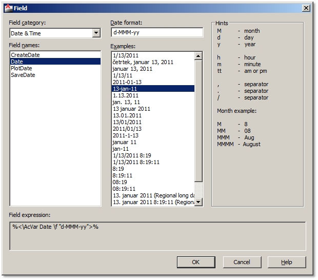
Date&Time Various fields to add date and time stamps to your drawing: CreateDate, Date, PlotDate and SaveDate. Under Date format you can choose several predefined examples of date formats to insert. Document Fields related to working in a document: Author, Comments, Filename, Filesize, HyperlinkBase, Keywords, LastSavedBy, Subject and Title. Field formats correspond to field type. Linked Insert Hyperlinks as quick links to open other documents, drawing views or web pages. Related to: 15. Add Links for a Quick Access to Other Documents, Saved Views and Web Page Objects Display information about selected objects (area, length, etc.), named object types, blockplaceholders and even calculate data using formulas. For example, you can insert a field as an object’s area and when you stretch the same object, the new area will be recalculated automatically. Other Rarely used but available are fields related to System Variables and Diesel-/Lisp-Expressions. Plot Add automatically updated information about a plotted drawing: DeviceName, Login, PageSetupName, PaperSize, PlotDate, PlotOrientation, PlotScale and PlotStyleTable. SheetSet Fields to automate sheet set data. Insert Field
Fields can be inserted as a stand-alone text or within a text, attribute, attribute definitions and even in table cells.
Inserting field within attribute definition
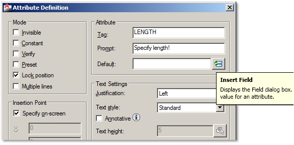
When creating, e.g. dynamic blocks you can insert field within an attribute definition. Attribute Definition dialog box / Click Insert Field button instead of typing the default value / Select field. Inserting field in table cells
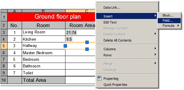
Select a Table cell / Shortcut menu / Insert Field Update Field
All inserted fields will be automatically updated after you make changes to your drawing file or geometry. You can control which and when field data gets updated by setting FIELDEVAL system variable. You can set the following controls:
0 = not updated 1= updated on Open 2= updated on Save 4= updated on Plot 8= updated on use of Etransmit 16= updated on regeneration Default value is set to 31, which is the sum of all updated values; therefore all of them are active. So when you, e.g. stretch an object with an area field definition, just type RE (short for Regen command) and new area field value will be updated. Modify Fields
Field definitions can be modified after field has been inserted in your drawing, e.g. modifying broken links or assigning length object property field instead of area. When a field link gets broken, you will notice a ### sign instead of the field value. You can modify fields following next steps:
Modify a stand-alone field or field within a text Both of them can be modified the same way as a standalone field is actually a multiline text field. 1. Double-click on inserted field to activate Text Editor. 2. Select field to highlight it / Shortcut menu / Edit Field 3. Choose different field options. Modify field in a table cell
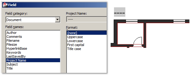
1. Double-click a cell with inserted field to activate it 2. Select field to highlight it / Shortcut menu / Edit Field 3. Choose different field options. If a field text displays these characters - - - it means that the required information of the inserted field is still unknown. For example, inserted SaveDate field will display these signs until you save the drawing. Format Fields
Field text format style depends on the active Text Style when inserting a field. You can always change its text properties after it’s already been inserted like you do with normal text (Properties palette or Text Editor).
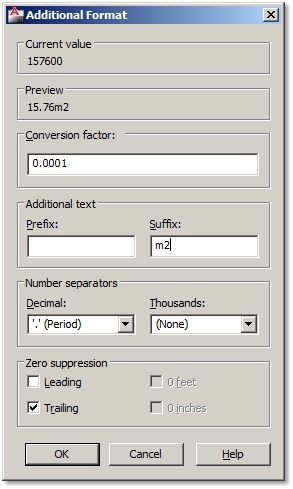
Field format in the Field dialog box usually corresponds to a chosen field name. For example, you can choose from many date formats or options to display a file name. However, fields which are linked to geometry, e.g. length or area of an object, have some additional formatting options. Let’s say your object area field is displayed in squared centimeter units, but you would like to display it in squared meters units: Format options in Additional Format dialog box:
1. Field dialog box / Additional format button / Additional Format dialog box 2. Conversion factor – specify conversion factor to use on the current value, e.g. 0.0001 (1cm2 = 0.0001m2). 3. Prefix – specifies prefix to be added in front of the current value. 4. Suffix – specifies suffix to be added at the end of the current value, e.g. m2. 5. Number separators – specifies a decimal separator and the formatting for numbers over 1000. 6. Zero suppression – suppression of leading (0.100 = .100) and trailing (0.100 = 0.1) zeros in decimal values or of feet (0'-3 1/2" = 3 1/2") and inches (3'-0" = 3') with a zero value. If you copy and modify a field, you will have set additional formatting all over again. Field values or texts have a gray background color so that you can easily recognize them in your drawing. Gray shade will not be plotted, but if it bothers you anyway, you can turn it off by setting FIELDDISPLAY system variable to 0. Create and Insert a Custom Field
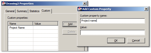
All custom drawing properties can be inserted as fields from the Document field category.
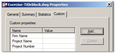
Create a custom field 1. File / Drawing Properties / Custom tab 2. Add button / Specify Custom property name, e.g. Project name / Ok / Ok Insert a custom field
1. Ribbon / Insert tab / Data panel / Field 2. Field Category options / Document 3. Field names / Project name 4. Format / Uppercase 5. Specify field insertion point Modify a custom field
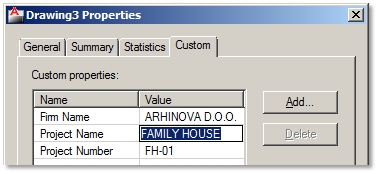
1. File / Drawing Properties / Custom tab 2. Click Value cell of the Project name / Enter the name of Project name, e.g. Familiy House / Ok 3. Regenerate drawing (RE). You can use the same procedure to create many custom fields.
8. Create Automatic Title Blocks
It can be quite annoying to change the same data in many title blocks in your drawing when it needs to be updated. Therefore it is best to organize or create them in a way that you will change data only once and the rest of the common data will update automatically. A title block should be created using the following objects:
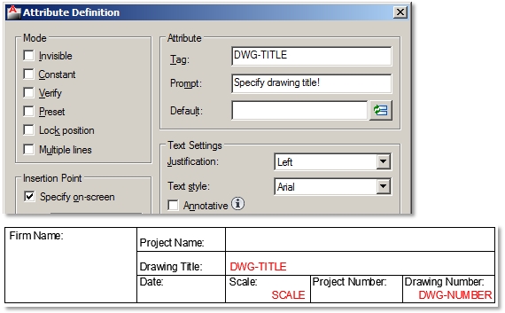
- Table geometry (black color). - Text to describe inputs (black color). - Attributes to specify single drawing properties, e.g. drawing name or number (red color). - Fields to specify project data which is common to many drawings, e.g. project’s or investor’s name (blue color). Table Geometry and Text Descriptions
1. Open a new drawing.
2. Draw table geometry, e.g. Polyline. 3. Use Multiline or Single Line Text to add description of inputs. Create and Insert Attributes
Ribbon / Home tab / Block drop-down panel / Define Attributes
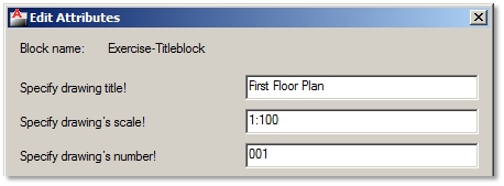
Create and insert 3 types of attributes each at a time: 1. Drawing title: Tag (DWG-TITLE), Prompt (Specify drawing title!), Justification (Left) 2. Scale: Tag (SCALE), Prompt (Specify drawing’s scale!), Justification (Right) 3. Drawing number: Tag (DWG-NUMBER), Prompt (Specify drawing’s number!), Justification (Right) Insert Predefined Date and File Name Fields
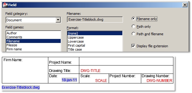
Insert date as a predefined field:
1. Ribbon / Insert tab / Data panel / Field 2. Field Category options / Date&Time 3. Field names / Date 4. Examples / Select the date format / Ok 5. Specify field insertion point. Insert file name as a predefined field: 1. Ribbon / Insert tab / Data panel / Field 2. Field Category options / Document 3. Field names / Filename 4. Format / Filename only / Ok 5. Specify field insertion point. Create and Insert Custom Fields
Insert a custom field
1. Ribbon / Insert tab / Data panel / Field 2. Field Category options / Document 3. Field names / Firm name 6. Format / Uppercase 7. Specify field insertion point. Because the custom filed data isn’t yet filled out in the Drawing Properties dialog box, field text displays as characters - - -.
If you decide to use custom fields as drawing properties in your title block, make sure, that the same drawing properties are also specified in the drawing into which you will insert this title block. So, to avoid typing and re-creating custom fields as drawing properties in each drawing with inserted title block, it is advisable to save custom drawing properties, thereby custom title block’s fields in a drawing template (.DWT). If you use the same drawing template to start of your projects, then custom fields in inserted title block will work just fine (links won’t be broken). Insert Title Block as a Block
If you drew your own title block in a new drawing, just save it and you will be able to insert it in any other drawing as a block. Before you do that, make sure you don’t forget to specify title blocks base point.
1. Type BASE. 2. Specify base point, e.g. bottom right corner. 3. Save title block .DWG file. Open your project drawing and insert a title block. 1. Ribbon / Home tab / Block panel / Insert 2. Browse for title block file. 3. Specify insertion point of title block. Fill out the data in title block: 1. Edit Attributes dialog box will automatically open after specifying insertion point. Fill out attribute data. 2. File / Drawing Properties / Custom tab
3. Click Value cells to fill out custom field title block data. Modify the data in title blocks:
You can change different attribute data in the same title blocks in a drawing. Double click any object of the title block and change data in Enhanced Attribute Editor dialog box. Custom field data is changed only once in the Drawing Properties dialog box. The same custom fields in all title blocks will update. Extra tip: If Edit Attributes dialog box doesn’t open, and you are prompted to fill out attribute data at command lines, the set ATTDIA system variable to 1. This will turn on the display of attribute dialog box. 9. Automate Length or Area Calculations
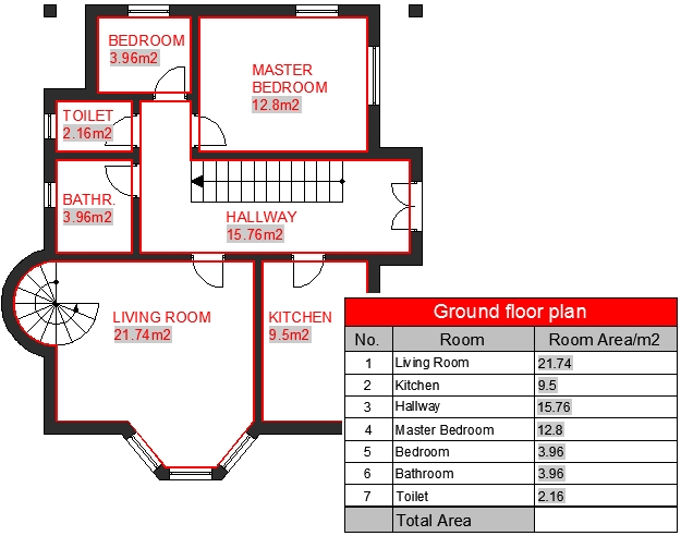
Objects´ area or lengths are often used in different calculations, like area calculations, etc. As plans get modified and object dimensions change you’d normally have to recalculate all area calculations and change data in your drawing. Wouldn’t it be great, if you just stretched a room in your drawing and the following data automatically updates?
- Room’s area size in your room description, - Room’s area size in the floor plan area calculations table, - Total area calculation in the floor plan area calculations table. Insert Fields in Room Area Descriptions
1. Draw closed boundaries of all room areas with polylines.
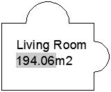
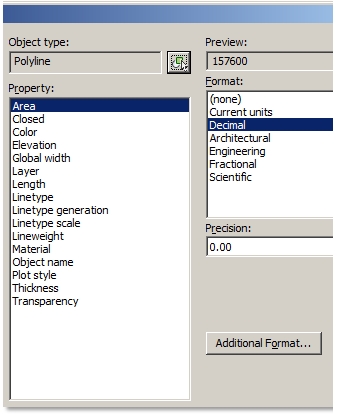
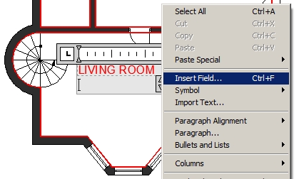
2. Ribbon / Home tab / Annotation panel / Multiline Text 3. Specify text bounding box and type in any text, e.g. Living Room, and press Enter to the next line. 4. Shortcut menu / Insert Field 5. Field Category options / Objects
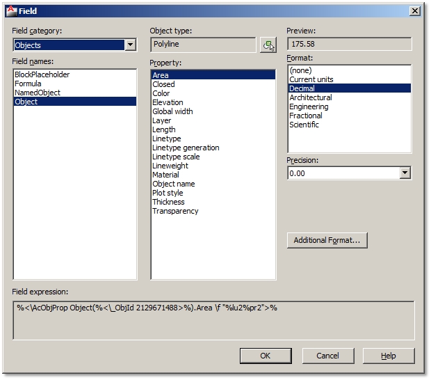
6. Field names / Objects 7. Object type / Select Object button 8. Select a closed boundary of the living room area in a drawing. 9. Property / Area 10. Format – choose your unit format and precision 11. Additional format button – additional formatting options only / Ok / Ok 12. Type suffix for squared units ´m2´. 13. Close Text Editor. Insert area fields for all other room area descriptions. You can also copy the one you’ve created to other rooms, but you will have to modify area fields to link proper rooms to their area boundaries. Insert Fields in the Floor Plan Calculations Table
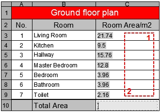
Using Table command design and insert your own table. Activate cells to normally type in text, e.g. Living room. Room areas must be inserted as fields linked to closed room boundaries.
1. Click the table cell where you want to insert room area. 2. Shortcut menu / Insert / Field 3. Field Category options / Objects 4. Field names / Objects 5. Object type / Select Object button 6. Select a closed boundary of the living room area in a drawing. 7. Property / Area 8. Format – choose your unit format and precision 9. Additional format button – additional formatting options only / Ok / Ok Repeat the procedure for all room areas. Create Field Formulas to Calculate the Table Data
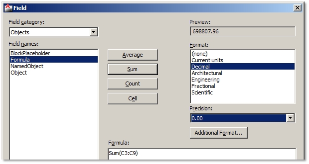
Data in tables can be calculated using field formulas. For example, to calculate the total of all room areas:
1. Click the table cell where you want to insert the total room area. 2. Shortcut menu / Insert / Field 3. Field Category options / Object 4. Object type / Formula 5. Select Sum button. Modify Room Size in Your Drawing and Update All Area Calculations
If you stretch some room sizes and regenerate the drawing (RE), all fields linked to stretched room boundaries will recalculate their area data.
10. Use Object Snap to Copy Geometry from PDF Files
You can use a PDF file as an underlay in your drawing and use object snaps to quickly draw on it.
1. Select the outer frame of your inserted PDF underlay. 2. Contextual ribbon PDF Underlay tab / Options panel / Turn on Enable Snap 3. Status Bar / Turn on Object Snap button / Select object snaps
4. Use Draw commands to draw across your PDF underlay using object snaps. 11. What AutoCAD Can´t Do, Lisp Applications Can
The great thing about AutoCAD is that it supports different applications to the program. Some are complex and probably cost a lot of money, but you can also find a lot of simple free Lisp plug-ins that can help you speed up or simplify some operations. You can find a whole lot on the internet.
Download Lisp File
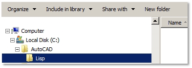
1. Create a folder on your hard drive to store all AutoCAD Lisp files in the future, e.g. C:\AutoCAD\Lisp.
2. Browse the internet for a lisp file (.LSP). Try browsing entries like: AutoCAD free lisp (you might also add short descriptions of an AutoCAD operation you seek for).
3. Download the lisp file from the internet to your, e.g. C:\AutoCAD\Lisp, on your hard drive. 4. If the downloaded file is saved in .TXT file format, rename its file extension to .LSP. The reason why some Lisp applications are saved in .TXT file format is because they are programmed and saved as text files. Authors also usually add some description of their application and maybe even installing instructions. So, reading Lisp file in .TXT format file can provide you some valuable information. You just rename file extensions to change one file type to another. However, if you want the application to work in AutoCAD, the file must have an .LSP file extension. Add Support File Search Path in AutoCAD to Your Lisp File
1. Tools / Options / Files tab
2. Click + sign in front of Support File Search Path list 3. Click Add button / Click Browse button / Browse for folder with stored Lisp files, e.g. C:\AutoCAD\Lisp. Load Lisp Application
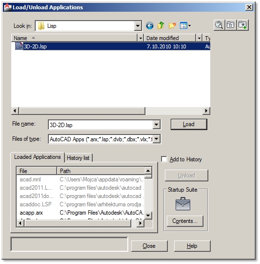
1. Tools / Load Application
2. Load/Unload Applications dialog box / Browse and select your Lisp file / Click Load button / Close 3. Lisp application is launched by typing usually its program name at command lines. Otherwise check on the internet where you downloaded your lisp file from, and see if author specified a launching command. You can also change .LSP file to .TXT file, open text file, and see if author wrote it down. Load Applications Automatically Every Time You Launch AutoCAD
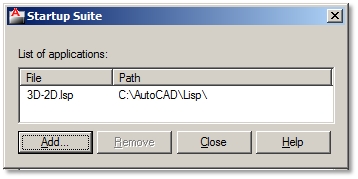
Normally you will have to load applications in every new drawing. If you want to skip this process, simply set to load applications every time you launch AutoCAD.
|
Additional AutoCAD tricks
|


