AutoCAD Tips and Tricks - File Management1. Add Links for a Quick Access to Other Documents, Saved Views and Web Pages
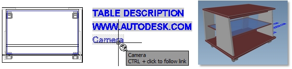
Using Hyperlinks you can connect to web pages, open other documents and display saved views directly from your drawing using just one click (Ctrl+click).
Hyperlink to Other Files
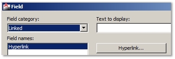
1. Ribbon / Insert tab / Data panel / Field
2. Field Category options / Linked 3. Field Names options / Hyperlink / Hyperlink button 4. Insert Hyperlink dialog box / Link to options / Existing File or Web Page / Browse for File button
5. Browse for a file / Open 6. Insert Hyperlink dialog box / Type Text to display as a link / Ok / Ok 7. Specify insertion point of hyperlink. 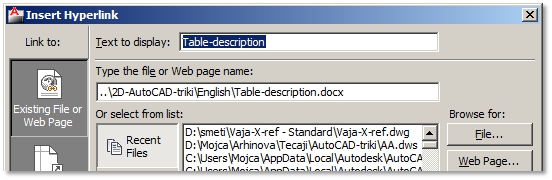
Hyperlink to Web Pages
1. Ribbon / Insert tab / Data panel / Field
2. Field Category options / Linked 3. Field Names options / Hyperlink / Hyperlink button 4. Insert Hyperlink dialog box / Link to options / Existing File or Web Page / Browse for Web Page button 5. Browse the Web dialog box / Enter the Name or URL to you website / Ok 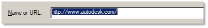
8. Insert Hyperlink dialog box / Type Text to display as a link / Ok / Ok
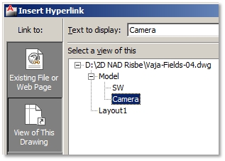
9. Specify insertion point of hyperlink. Hyperlink to Saved Views
2. Fixing Slow and Damaged Files
If your drawing behaves strangely, e.g., takes a long time to open or runs slow, this could be a sign that the file is damaged. You can try to fix errors using two AutoCAD auditing tools; however it is not necessary that they will be successful.
Fix errors in an Opened Drawing

Application menu / Drawing Utilities / Audit / Confirm Yes to fix any detected errors.
Press F2 (Text Window) to see the fixing report, how many errors were found and fixed. It is recommended you don’t continue your work in the same drawing. Save it as a different drawing! Fix a Drawing That Cannot be Opened

Launch AutoCAD / Application menu / Drawing Utilities / Recover / Recover / Browse the .DWG file / Open
You can see the fixing report, how many errors were found and fixed in a dialog box or Text Window. It is recommended you don’t continue your work in the same drawing. Save it as a different drawing! 3. Remove Unused Content from Your Drawings
When working with large drawings, it is quite likely that you will create a pile of unused Blocks, Layers, various Styles, etc. that you don’t use. If everything works fine, you will have no problem to continue with your drawing, but when it starts to respond slowly or its file size becomes too big, it is recommendable to clean up these unused items.
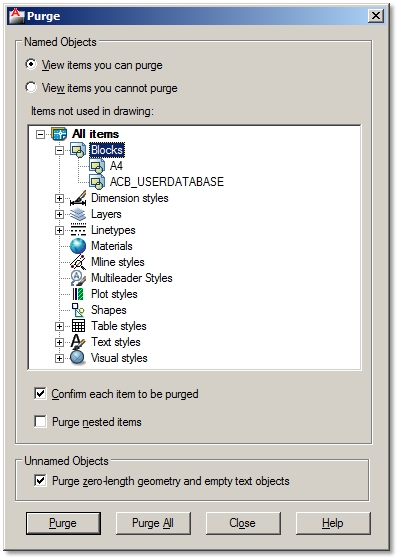
1. Application menu / Drawing Utilities / Purge 2. Purge dialog box / Named Objects options / View items you can purge 3. Click an item name, e.g. Blocks to purge blocks only. 4. Purge All button – purges all items in your drawing. 5. Confirm Purge dialog box – confirm purging one or all chosen items. 6. Purge zero-length geometry and empty text objects – erases invisible text, e.g. text space only, and geometry with 0 length.
4. External References
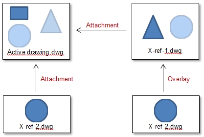
X-ref is an AutoCAD term for external reference to another AutoCAD file directly from your active drawing. Referenced drawing and your active drawing appear as one, but in fact the X-ref drawing acts as an underlay. Its advantages are:
- Many people can work on different sections of the same project at the same time. - You can see a complete project in your active drawing; thereby avoid any mistakes or collisions. - File sizes with X-ref drawings are smaller than the one where sections are inserted as blocks. - You always see the latest version of your X-ref file in your active drawing without re-attaching it. - When your coworker saves changes to your X-ref file, you simply get a notification to update them. - X-refs can be attached, removed or inserted to your active file at any time. Attach an X-ref Drawing
1. Ribbon / Insert tab / Reference panel / Attach
2. Browse for referenced file. 3. Attach External Reference dialog box: 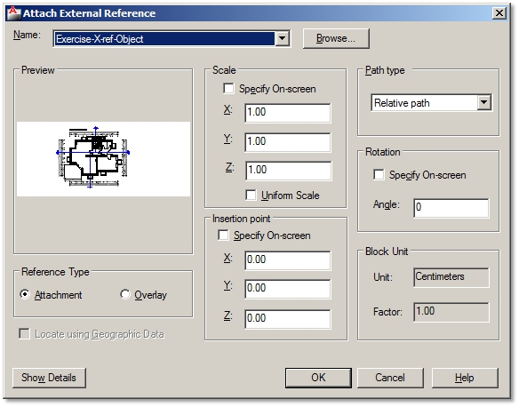
Scale:
If X-ref drawings used the same drawing units, set Scale to 1. Insertion point: It is recommended that all X-ref files refer to the same base point; thereby insertion point. Path Type: Attached X-ref drawing file is read from its saved location. If you relocate this file to a different project folder or send your drawings to other people, this path could be broken and the X-ref drawing won´t be seen in your active drawing. You can select three different ways of remembering X-ref file path: Full path – X-ref file is read from an absolute path (the file must be located in the same folder order). Relative path – remembers the folder order between the X-ref and active file. You can move the project folder to a different folder or hard drive, but you shouldn’t move one of the files to a different folder. No path – X-ref and active file must be located in the same folder.
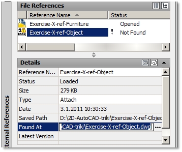
Manage an X-ref Drawing
Open an External Reference Palette:
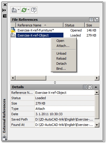
Ribbon / Insert tab / Reference panel / Click on the angled arrow or Select X-ref drawing / Contextual Ribbon External Reference / Options panel / External References Shortcut menu on the name of the X-ref file and select one of the following:
Update Lost X-ref File Paths
Make Changes in Your X-ref File
Separate from your active drawing:
1. File / Open - The easiest and least confusing way is to simply Open your X-ref file, make and save changes. Within your active drawing: 2. External Reference palette / Right-click on the name of X-ref file / Open. 3. Select X-ref drawing / Contextual Ribbon External Reference / Edit panel / Edit Reference In-Place X-ref drawing is opened inside your active drawing. As you can see the rest of your active drawing it is easier to make those changes in your X-ref drawing that depend on geometry in your active file. For comparison, if you open your X-ref file with an Open command, you will only see the geometry of your X-ref drawing and none from your active file. Extra tip: If you work on the project with your coworkers, you might receive a notification that you cannot open your X-ref file as it is Read-only. This means that someone in your working group has opened this file before you did. This is a safety precaution, and you will not be able to save changes to this File until your coworker closes it first. Change Graphic Appearance of X-ref Drawings
Clipping X-ref drawings:
1. Select X-ref drawing / Contextual Ribbon External Reference / Clipping / Create Clipping Boundary 2. Specify Clipping Boundary – pre-drawn Polyline, Polygonal or Rectangular. 3. Select X-ref drawing / Contextual Ribbon External Reference / Clipping / Remove Clipping – Restores clipped X-ref drawing. X-reference fading: 4. Ribbon / Insert tab / Reference panel / X-ref Fading 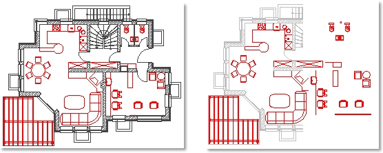
Reconcile X-ref Layers
Layers that belong to X-ref drawing are automatically renamed by adding a file name as a prefix in front of a layer name. Layer organization in an active drawing is therefore not disturbed. You can set properties to X-referenced layers, but you cannot make them current.
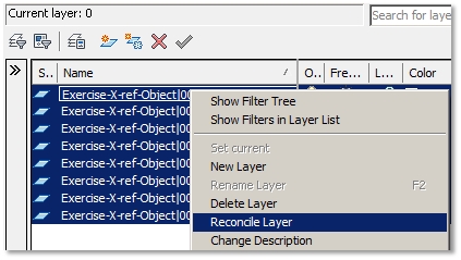
When you attach an X-ref drawing you might get a notification (bottom right corner) about new unknown or unreconciled layers in your drawing. To some this information seems valuable, but many may find it annoying if messages to reconcile new layers keep popping up during various operations, e.g. before plotting. To resolve this you can either reconcile new layers or turn off layer evaluation control. Reconcile new layers: 1. Click View unreconciled new layers in Layer Properties Manager. 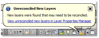
2. Select all unreconciled layers / Right-click / Choose Reconcile Layer from the menu.
Turn off new layer evaluation control:
3. Set the system variable LAYEREVALCTL to 0. |
Additional AutoCAD tricks
|

|
|